How to Choose the Best T Beam Welding Line
Choosing the right T beam welding line starts with the beam, not the brochure. Web height, flange width, plate thickness, weld length, and daily output all shape the decision. A line built for occasional custom sections may struggle with repeated high-volume work. An oversized system can consume floor space and budget without improving quality. Measure actual parts, including their variation.
Welding automation specialist Daniel Mercer offers a useful rule: “Choose the line around your real beam mix, not your best-case drawing.” Treat that as a practical reminder, not a substitute for technical checks. Compare welding method, clamping, torch access, travel speed, and options for handling distortion. Watch how the machine holds a long web upright while flanges meet it squarely. Small alignment errors can become visible after welding. They matter.
This guide explains how to compare capacity, automation, weld quality, controls, service support, and total operating cost. Ask suppliers to demonstrate representative sections, not just ideal samples. Review setup time, operator access, consumables, and maintenance requirements. Request clear acceptance criteria and a realistic production estimate. A fast cycle is not always a good cycle. No line removes every trade-off, and catalog figures rarely tell the whole story. The best choice is the one that fits your parts, people, and production plan—with enough flexibility for what may change.
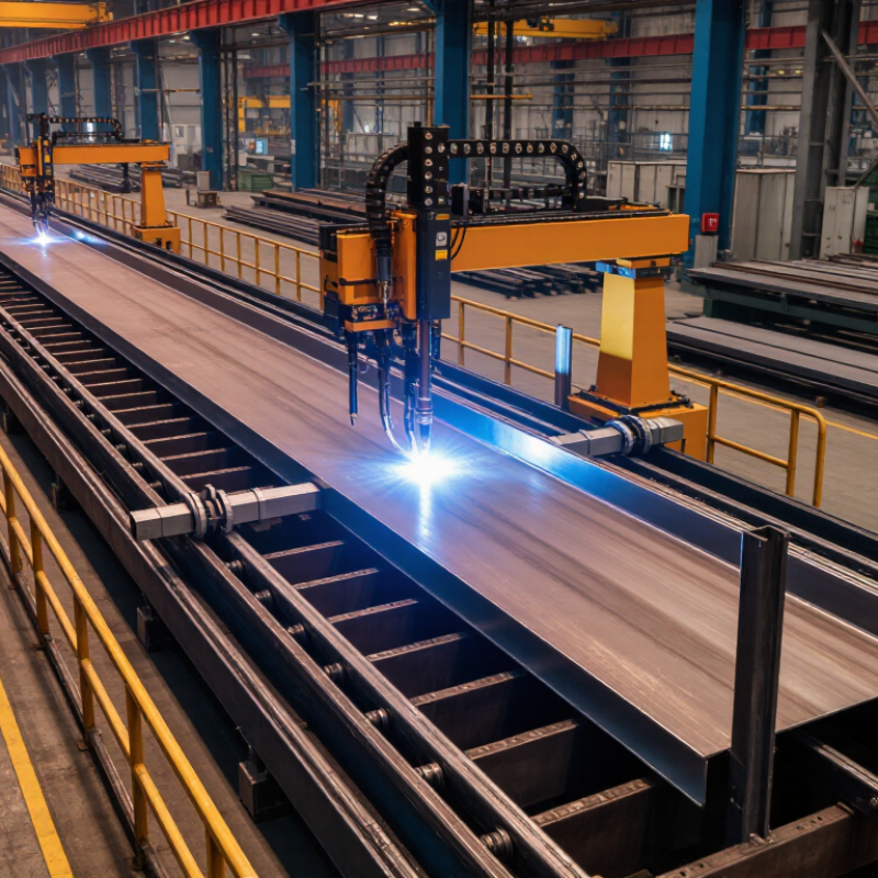
Define T-Beam Sizes, Web Thicknesses, Flange Widths, and Required Capacity
Start with the fabrication envelope, not a machine’s headline speed. Record minimum and maximum web height, web thickness, flange width, flange thickness, and beam length. Include plate grade, joint gap, and required weld size; each affects torch access and heat input. Example: a 600 mm × 12 mm web with 250 mm × 16 mm flanges. Check clamping, tracking, tack welding, and straightening against that geometry. Small details matter. Do not assume. A test run with your actual plates can reveal fit-up problems that drawings miss.
Define capacity as finished beams per shift, tonnes per month, and metres per hour. One figure alone can mislead. Separate welding speed from real output by accounting for loading, fit-up, changeovers, and rework. The World Steel Association’s World Steel in Figures 2024 reports 1,892.2 million tonnes of crude steel production worldwide in 2023. That figure gives industry context, not a shop-floor target. The American Welding Society’s 2020 workforce report projected demand for 330,000 welding professionals in the United States by 2028. Include available operators in shift assumptions. Treat rated output as provisional until timed production trials confirm it.
Estimate Output Using Typical SAW Deposition Rates of About 5–20 kg/h
How to Choose the Best T Beam Welding Line
Estimate Output Using Typical SAW Deposition Rates of About 5–20 kg/h
A submerged arc welding line may deposit roughly 5–20 kg of weld metal per hour. Treat this as a planning range, not a guaranteed production rate. Actual deposition depends on wire size, current, travel speed, joint design, and the number of passes. A large fillet weld on a thick T beam can consume far more wire than a light structural joint. Small differences add up.
That matters.
When comparing line capacity, estimate weld metal required per beam, then divide by a realistic hourly deposition rate. For example, 10 kg of weld metal at 10 kg/h suggests about one hour of arc time. It does not include loading, alignment, tack welding, repositioning, inspection, or maintenance. Those minutes can quietly shape the whole shift. Ask suppliers for trials using your beam dimensions and weld details, and record both arc-on time and total cycle time. One estimate may still be wrong; production has a way of exposing assumptions. Choose equipment with enough adjustment range for your usual beam sizes, rather than selecting solely by the highest quoted deposition rate.
How to Choose the Best T Beam Welding Line - Estimate Output Using Typical SAW Deposition Rates of About 5–20 kg/h | Combined SAW Deposition Rate | Example Weld Metal per T Beam | Arc Time per Beam | Arc-Only Output per 8-Hour Shift | Planning Estimate per Shift |
| 5 kg/h | 3.39 kg | About 41 minutes | About 7 beams | 4 beams |
| 10 kg/h | 3.39 kg | About 20 minutes | About 14 beams | 9 beams |
| 15 kg/h | 3.39 kg | About 14 minutes | About 22 beams | 14 beams |
| 20 kg/h | 3.39 kg | About 10 minutes | About 29 beams | 19 beams |
| Use the planning estimate as an initial comparison, not a guaranteed production rate. |
Example basis: Each beam has two 12 m longitudinal fillet welds with a 6 mm leg size. An idealized triangular fillet profile gives approximately 0.283 kg of weld metal per metre across both welds, or about 3.39 kg per beam. The estimate assumes 5 productive arc hours in an 8-hour shift and applies a 65% planning factor to allow for handling and other non-arc time. Deposition rate means the combined rate of the active welding heads. Actual output varies with joint design, welding procedure, beam dimensions, repositioning, fit-up, and line availability.
Match Welding Power, Positioning, and Heat Input to the Required Joint
Choose a T-beam line by the joint, not by the machine’s maximum amperage. A thick flange joined to a thinner web can need different power and travel settings. Excessive heat may widen the weld and pull the flange out of square; insufficient heat can compromise fusion. AWS’s Welding Handbook describes arc energy calculations using voltage, current, and travel speed. For example, 28 volts and 420 amperes at 300 mm/min gives about 2.35 kJ/mm before process-efficiency correction. ISO/TR 18491:2015 provides guidance for measuring welding energy. Keep the calculation method consistent when comparing procedures.
Positioning matters just as much. A line that holds the beam steady and presents the joint consistently can reduce starts, stops, and awkward torch angles. Check whether fixtures support the web without restricting access to the root and toe. For long beams, trial runs can reveal drift that a short coupon will not. Small details count. Measure flange movement before and after welding, and record the actual travel speed, not just the programmed setting. A tidy parameter sheet can still miss a poor fit-up; that is worth checking twice. Adjust heat input only alongside the specified joint design, material thickness, and qualified welding procedure.
Check Structural Welding Quality Against AWS D1.1 and ISO 3834
When choosing a T beam welding line, check how it controls fit-up, heat input, and distortion. These details affect whether the web stays square to the flange during long weld runs. Ask for sample welds using steel thicknesses and joint preparations similar to your production work. Inspect the weld profile, start and stop points, and any undercut or porosity. Small gaps matter. A line that produces repeatable results makes qualification and inspection more manageable, but automation alone does not guarantee sound welds.
AWS D1.1 sets requirements for structural steel welding, including welding procedures, welder qualifications, and inspection criteria. Confirm that the proposed process can support the applicable qualified procedure and required records. ISO 3834 addresses quality requirements for fusion welding, from coordination and personnel competence to equipment control and traceability. It can help assess whether quality practices are consistent across production.
Neither standard is a shortcut to good workmanship. Ask how the supplier records parameters, handles repairs, and checks alignment after welding. Then review actual production evidence, not just a checklist. One point is easy to overlook: a fast line may still need careful adjustment when beam dimensions or plate thickness change. That trade-off deserves a practical trial.
Compare Automation, Straightening, and Material Handling Options
A T beam welding line should be compared as a complete process, not by welding speed alone. The International Federation of Robotics’ World Robotics 2024 report recorded 541,302 industrial robot installations worldwide in 2023. That figure shows how widely automation is being adopted, but it does not guarantee that a highly automated line suits every beam mix. Check whether robots can handle your flange widths, web heights, and order changes without lengthy reprogramming.
Straightening capability matters just as much. Ask for measured web and flange distortion after welding, using representative beam sizes and weld sequences. Confirm how the straightening unit adjusts for different profiles, and whether operators can access rolls for inspection. A fast line that needs frequent correction can lose its advantage. Small details matter.
Material handling sets the rhythm between stations. Compare roller-table capacity, crane or transfer requirements, and how the system supports long beams without sagging. Deloitte and the Manufacturing Institute’s 2024 study estimated that 1.9 million U.S. manufacturing jobs could remain unfilled by 2033. That broad workforce projection is not welding-line-specific, but it reinforces the value of reducing repetitive handling. Still, automation can add maintenance and training demands. I would not choose by peak output alone; ask suppliers to demonstrate a realistic changeover and trace one beam from loading to discharge. The less glamorous test is often the useful one.